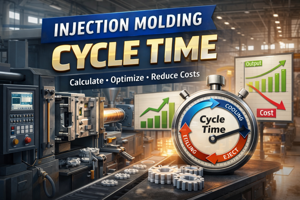
Using an Injection Molding Cycle Time Calculator
Instead of manual estimation, many engineers now use tools like:
Injection Molding Cycle Time Calculator
These tools allow you to:
- Input wall thickness and material
- Adjust temperature parameters
- Estimate cooling and total cycle time instantly
- Compare design options before tooling
This helps during:
- Quotation stage
- Product design optimization
- Cost estimation
Common Mistakes in Cycle Time Estimation
Avoid these typical errors:
❌ Ignoring Cooling Time
Cooling is the dominant factor — never underestimate it.
❌ Using Average Thickness Instead of Maximum
Always use maximum wall thickness, not average.
❌ Overlooking Mold Design
Cooling channels often matter more than material choice.
❌ Unrealistic Ejection Temperature
Incorrect assumptions can lead to major errors.
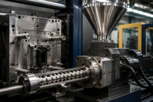
What Is Injection Molding Cycle Time?
Injection molding cycle time refers to the total time required to complete one full molding process, from injection to part ejection and mold closing.
A typical injection molding cycle includes:
- Filling (Injection)
- Packing / Holding
- Cooling
- Mold Opening
- Part Ejection
- Mold Closing
Cycle time is one of the most critical factors in plastic manufacturing, directly affecting:
- Production efficiency
- Cost per part
- Machine utilization
- Delivery lead time
Why Cycle Time Matters in Injection Molding
Understanding and optimizing injection molding cycle time can significantly impact your business.
1. Cost Reduction
Shorter cycle time = more parts per hour = lower unit cost.
2. Higher Production Capacity
Even a 1-second reduction can increase output dramatically in high-volume production.
3. Competitive Advantage
Faster production allows:
- Shorter lead times
- Better pricing
- Higher customer satisfaction
Injection Molding Cycle Time Formula
The total cycle time can be simplified as:
Cycle Time = Fill Time + Pack Time + Cooling Time + Mold Open/Close Time + Ejection Time
Among these, cooling time is usually the longest and most critical stage, often accounting for 50%–80% of the total cycle time.
How to Calculate Cooling Time
Cooling time depends on:
- Wall thickness
- Material properties
- Mold temperature
- Melt temperature
A simplified engineering formula is:
t = (s² / (π² · α)) × ln[(Tm − Tmold) / (Teject − Tmold)]
Where:
- t = cooling time
- s = maximum wall thickness
- α = thermal diffusivity
- Tm = melt temperature
- Tmold = mold temperature
- Teject = ejection temperature
This is exactly the logic used in your Cycle Time Calculator tool.
Key Factors Affecting Injection Molding Cycle Time
1. Wall Thickness (Most Important)
- Thicker parts = longer cooling time
- Cycle time increases exponentially, not linearly
👉 Rule of thumb:
Doubling wall thickness can increase cooling time by 4×
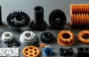
2. Material Type
Different plastics have different thermal diffusivity:
| Material | Cooling Behavior |
|---|---|
| PP | Fast cooling |
| ABS | Medium |
| PC | Slower |
| PA | Slower |
Choosing the right material can significantly reduce cycle time.
3. Mold Temperature
- Higher mold temperature = better surface finish
- But → longer cooling time
Balance is key.
4. Cooling System Design
A well-designed cooling system can:
- Reduce cycle time by 20–40%
- Improve part consistency
- Prevent warpage
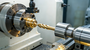
5. Machine Performance
- Injection speed
- Clamping speed
- Automation level
All influence non-cooling time.
Typical Injection Molding Cycle Time Ranges
| Part Type | Typical Cycle Time |
|---|---|
| Thin-wall packaging | 5–15 seconds |
| Consumer plastic parts | 15–40 seconds |
| Automotive parts | 40–120 seconds |
| Thick industrial parts | 120+ seconds |
How to Reduce Injection Molding Cycle Time
1. Optimize Wall Thickness
- Avoid unnecessary thickness
- Use ribs instead of solid sections
2. Improve Cooling Efficiency
- Conformal cooling channels
- Better water flow design
- Use high thermal conductivity materials
3. Use Faster Materials
- Switch to resins with higher thermal diffusivity
- Consider additives
4. Optimize Process Parameters
- Reduce holding time
- Adjust cooling cutoff point
- Fine-tune ejection timing
5. Upgrade Mold Design
- Better venting
- Efficient gating system
- Balanced runner system
Conclusion
Injection molding cycle time is a key driver of:
- Manufacturing efficiency
- Product cost
- Production scalability
By understanding how cycle time works and using tools like a cycle time calculator, manufacturers can:
✔ Improve productivity
✔ Reduce costs
✔ Make better engineering decisions