


Troubleshooting automotive injection molding defects is critical for maintaining strict automotive safety and finish requirements.
Common flaws range from structural warpage and sink marks to aesthetic flow lines and jetting. Success requires diagnosing whether the root cause lies in machine processing or mold tooling.
This guide will group all the 10 common problems to 3 groups while break down the exact machine adjustments and tooling modifications needed to resolve these obstacles and ensure your parts pass rigorous quality control.
TL;DR: Overview of What Problems Are Discussed
- Short Shots & Flash: Control injection pressure and clamp tonnage to balance cavity filling without mold separation.
- Dimensional Flaws: Fix warpage, sink marks, and voids by maintaining uniform wall thickness (≥ 0.8 mm) and extending hold times.
- Aesthetic Flaws: Eliminate burn marks, flow lines, jetting, and splay by slowing injection speeds, adding vents, and thoroughly drying hygroscopic resins.
- Tooling vs. Process: Address pressure and speed via machine settings first; redesign gates, cooling lines, and venting if tooling is the bottleneck.
Group 1: Filling and Pressure Challenges in Automotive Injection Molding
Filling and pressure problems can be mitigated by precisely matching your machine’s injection capacity to the mold’s clamping force. Adjusting injection speed, melt temperature, and mold venting will ensure the cavity fills completely without forcing material past the parting line.
→ Click to Learn: How to Choose the Right Injection Mold? Single, Multi-Cavity & Family Molds Compared
1. Short Shots
A short shot happens when molten resin solidifies before fully filling the mold cavity, which will leave an incomplete automotive component that must be scrapped.
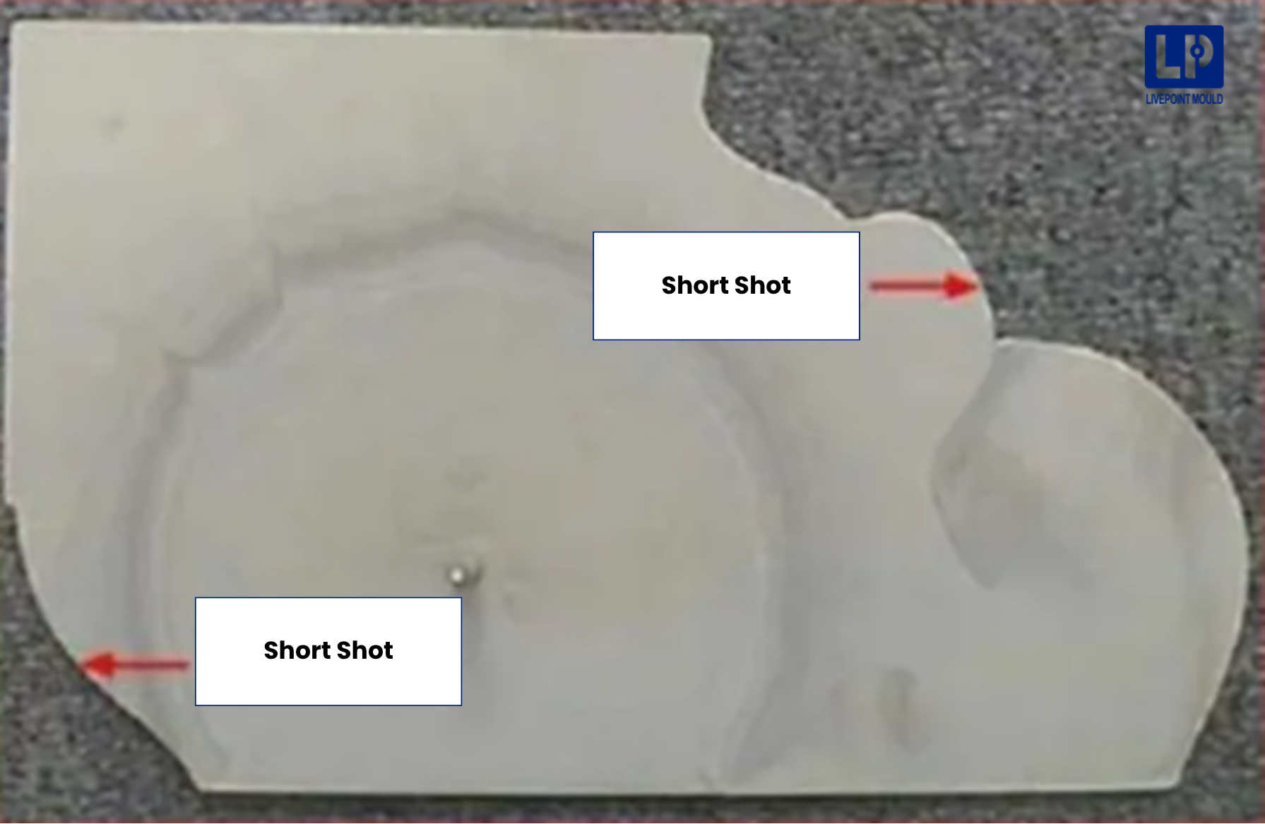
- Process Causes: The machine delivers insufficient injection pressure, low melt temperatures, or inadequate shot capacity.
- Tooling Causes: Poor mold venting traps air, which pushes back against the plastic flow. Narrow runners or gates can also choke the material.
- Solutions: Increase your injection speed and mold temperature to keep the plastic flowing. On the tooling side, widen the gates or cut strategic air vents near the end of the flow path.
2. Flash
Flash is a thin layer of excess plastic that escapes the mold cavity along the parting line. In high precision plastic injection molding, flash requires costly manual trimming and signals tool wear or extreme pressure.
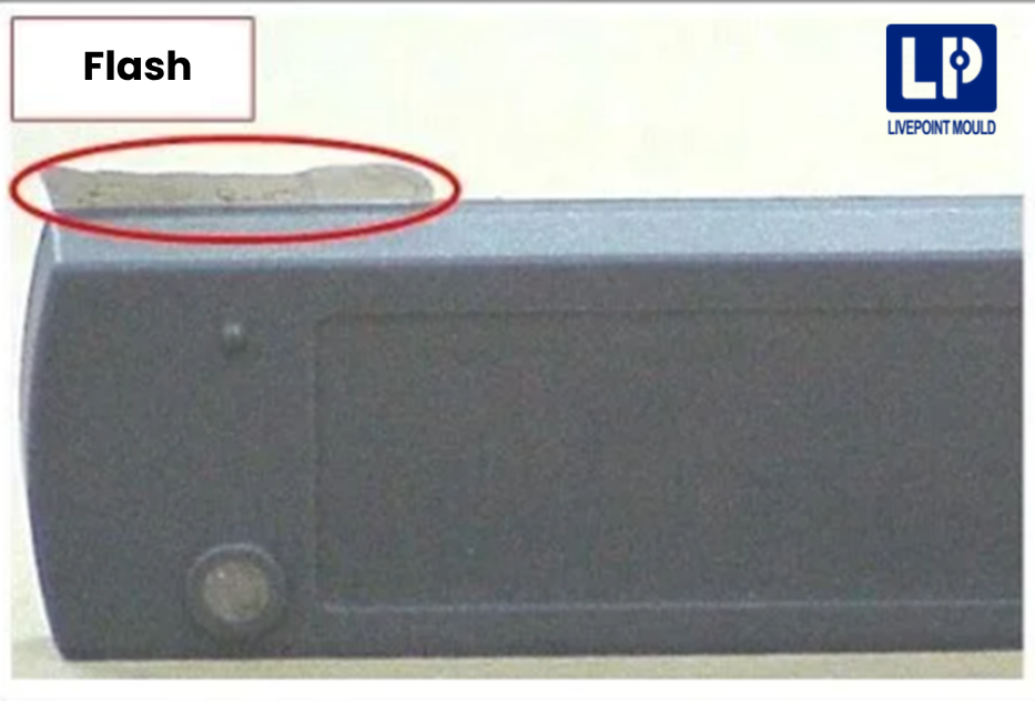
- Process Causes: Injection pressure exceeds the machine’s clamping force, pushing the two mold halves slightly apart.
- Tooling Causes: The mold steel has worn down, or the parting lines are mismatched (a condition known as poor “spotting”).
- Solutions: Increase your clamp tonnage or reduce the injection pressure. If the machine settings fail, the tool requires machine-shop maintenance to re-level the parting surfaces.
Group 2: Warpage Defect in Auto Parts Plastic
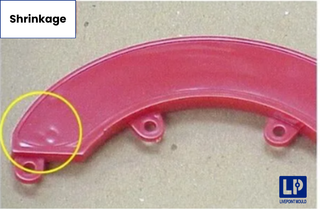
Shrinkage and distortion occur when different sections of a plastic part cool at unequal rates, pulling the material inward. You can prevent the warpage and distortion problems by maintaining uniform wall thicknesses, optimizing cooling channel design, and applying adequate packing pressure.
1. Sink Marks
Sink marks are visible depressions on the surface of thicker wall sections. They develop when the inner core of the plastic cools and shrinks, pulling the outer skin inward.
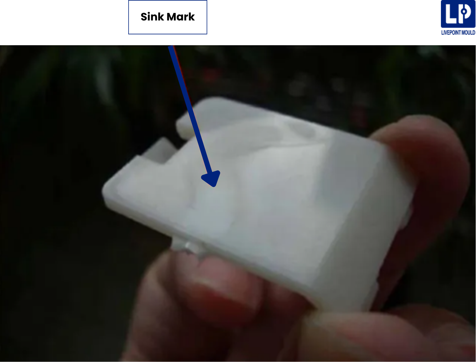
- Problems in the Process: Low packing pressure or inadequate holding time allows the gate to freeze before the cavity is fully packed.
- Tooling Causes: Wall thicknesses exceed the material’s structural limits, or internal ribs are too thick compared to the outer wall.
- Solutions: Increase your pack-and-hold pressure. During DFM, ensure ribbed features are no thicker than 60% (the minimum is 40%) of the adjoining wall thickness.
2. Warpage
Warpage is a permanent geometric distortion that ruins the dimensional stability of auto parts plastic. It happens when internal thermal stress causes the part to shrink unevenly during the cooling phase.
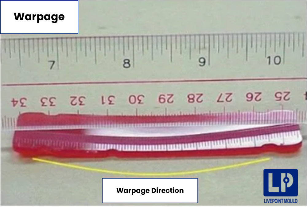
- Process Causes: Cooling temperatures are unbalanced between the two mold halves, or the cooling time is simply too short.
- Tooling Causes: The mold features poorly designed cooling channels or wildly inconsistent wall thicknesses.
- Solutions: Balance the mold surface temperatures. If the problem persists, redesign the water cooling lines to ensure uniform heat extraction across complex automotive geometries.
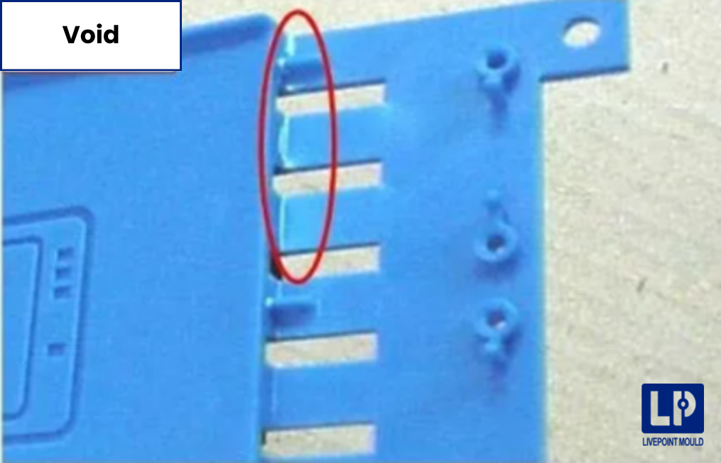
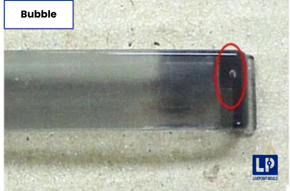
3. Vacuum Voids & Bubbles
Vacuum voids are trapped air pockets inside the molded part. While often invisible from the outside, they severely weaken load-bearing structural components.
- Process Causes: The machine applies insufficient packing pressure during the cooling phase.
- Tooling Causes: The gate freezes off too quickly. This prevents new material from feeding into the shrinking center of a thick section.
- Solutions: Apply higher holding pressure for a longer duration. Enlarge the gate size to delay freeze-off, allowing more material to pack the cavity.
Group 3: Aesthetic Surface Flaws in Automotive Plastic Injection Molding
Surface flaws are typically caused by trapped gas, moisture, or turbulent material flow. Properly drying the resins, optimizing gate placements, and controlling injection speeds to ensure smooth, uniform material entry can help.
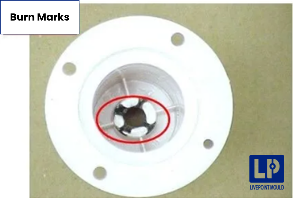
1. Burn Marks
Burn marks appear as dark, charred areas on the part’s surface. They are actually carbon deposits caused by trapped, superheated air combusting inside the mold.
- Process Causes: Injection speeds are too fast, compressing trapped air to ignition temperatures before it can escape.
- Tooling Causes: The mold design contains blind pockets or lacks adequate venting channels.
- Solutions: Reduce the injection speed to give air time to escape. Structurally, cut deeper or additional vents along the parting line.
2. Flow Lines
Flow lines are wavy, visible patterns that trace the physical path of the molten plastic. They generally show up near the gate where the material first enters.
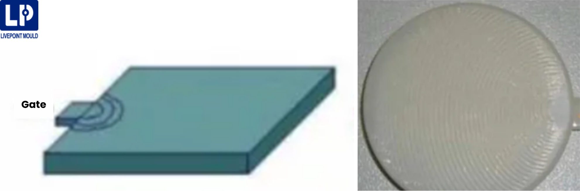
- Process Causes: Slow injection speeds or low melt temperatures cause the material to cool and stiffen unevenly as it moves.
- Tooling Causes: Sharp corners or abrupt changes in wall thickness disrupt the smooth flow of the plastic.
- Solutions: Increase the injection velocity to push the material through before it cools. Smooth out internal mold corners with larger radii.
3. Weld Lines (Knit Lines)
Weld lines form where two separate flow fronts of molten plastic meet and attempt to fuse. If the material is too cold, the fronts do not bond completely and that will create a visible line and a structural weak point.
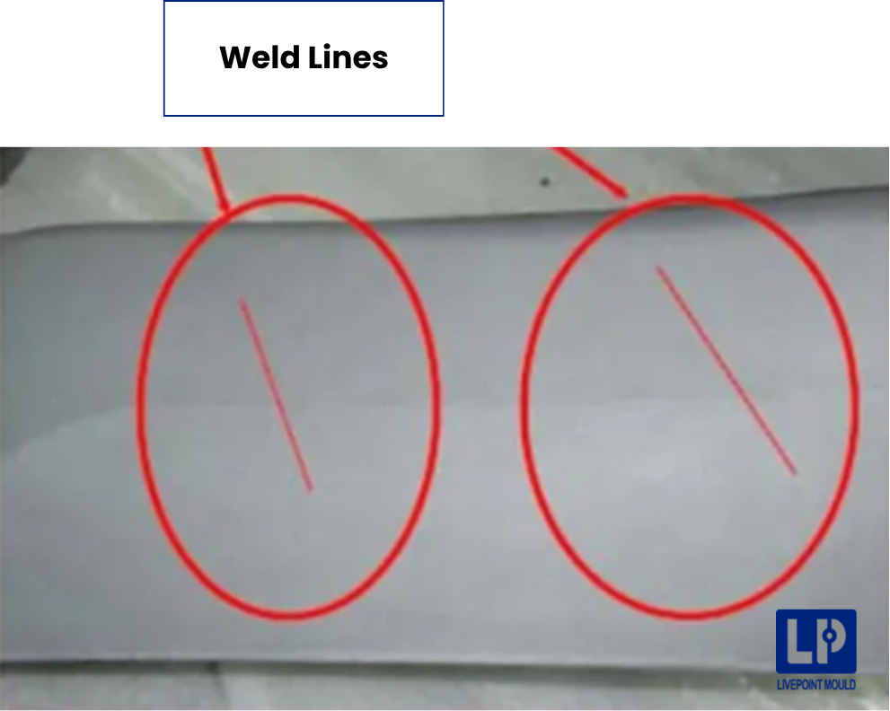
- Process Causes: Low melt temperatures or slow injection speeds allow the flow fronts to cool prematurely.
- Tooling Causes: The gate placement forces the melt to split around an obstacle (like a hole) and travel too far before converging.
- Solutions: Raise the melt and mold temperatures. Relocate the gate so the material flows uniformly without splitting, or add overflow wells.
4. Jetting
Jetting occurs when a high-velocity stream of molten plastic shoots straight through the gate and folds over itself like a snake. This creates a highly visible, weakened flow pattern.
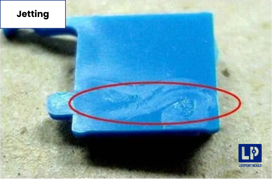
- Process Causes: The initial injection velocity is set too high.
- Tooling Causes: The gate is positioned to shoot directly into a thick, empty section of the cavity rather than against a restricting wall.
- Solutions: Program a profiled injection speed that starts slow and then speeds up. Redesign the gate so the plastic immediately hits a cavity wall upon entry, forcing it to spread smoothly.
5. Splay Marks (Silver Streaking)
Splay appears as splash-like, silvery marks on the surface of the part. It happens when expanding gas or moisture drags along the mold surface during injection.
- Process Causes: The resin was improperly dried, or excessive barrel heat caused the material to degrade thermally.
- Tooling Causes: Moisture condensed on a chilled mold surface.
- Solutions: Ensure hygroscopic resins (like nylon or ABS) are dried to the manufacturer’s specified moisture content (often below 0.02%). Lower the barrel temperature to prevent degradation.
Summary Table — Troubleshooting Automotive Injection Molding Flaws Quickly
| Defect | Primary Indicator | First Process Fix | First Tooling Fix |
|---|---|---|---|
| Short Shots | Incomplete part | Increase injection speed | Widen gates & runners |
| Flash | Excess plastic on edges | Increase clamp tonnage | Re-level parting lines |
| Sink Marks | Surface depressions | Increase holding pressure | Reduce rib thickness |
| Warpage | Distorted part geometry | Balance mold temperatures | Redesign cooling lines |
| Vacuum Voids | Internal air pockets | Increase holding time | Enlarge gate size |
| Burn Marks | Charred, dark spots | Decrease injection speed | Add air vents |
| Flow Lines | Wavy surface streaks | Increase injection velocity | Increase corner radii |
| Weld Lines | Visible fusion lines | Increase melt temperature | Relocate the gate |
| Jetting | Snake-like flow patterns | Use profiled injection speed | Aim gate at cavity wall |
| Splay Marks | Silvery surface splashes | Thoroughly dry the resin | Lower barrel temperature |
Livepoint expert tips: Always start with non-destructive process changes before modifying the mold steel.
FAQs on High Precision Plastic Injection Molding Troubles
1. What is plastic regrind in injection molding materials?
Regrind is recycled plastic leftover from previous molding cycles. While cost-effective, adding regrind alters the material’s melt flow index (MFI), which measures how easily the plastic flows, and increases the risk of contamination.
→ Injection Molding Cycle Time
High ratios of regrind increase the likelihood of splay marks due to degraded polymers trapping moisture. It also makes the melt viscosity unpredictable, which can trigger short shots or flash. To maintain automotive standards, limit regrind to a maximum of 10% to 20% and thoroughly dry it before processing.
2. Is the defect a “Process” issue or a “Tooling” issue?
A process issue can be fixed by the machine operator using the control panel. This includes adjusting temperatures, injection speeds, holding pressures, and cooling times.
A tooling issue requires a mold maker to physically alter the steel mold. This includes machining wider gates, cutting new air vents, or re-milling mismatched parting lines. Always attempt process adjustments first, as cutting steel is expensive and permanent.



 English
  Chinese
  German
  Italian
  Spanish
  French
  Russian
  Arabic
  Japanese
  Korean